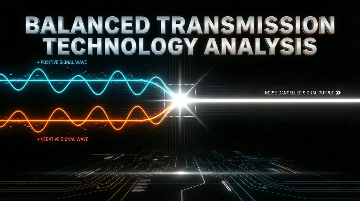
Balanced Transmission Technology Analysis
Unveiling the Core of Audio Transmission: Achieving High Noise Immunity with Balanced Systems In professional sound reinforcement, recording studios, and
Unveiling the Core of Audio Transmission: Achieving High Noise Immunity with Balanced Systems In professional sound reinforcement, recording studios, and
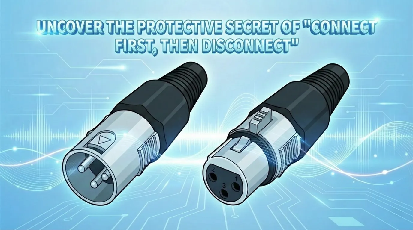
The Engineering Logic Behind “First Make, Last Break” Meta Description:Why is Pin 1 on an XLR connector designed to protrude
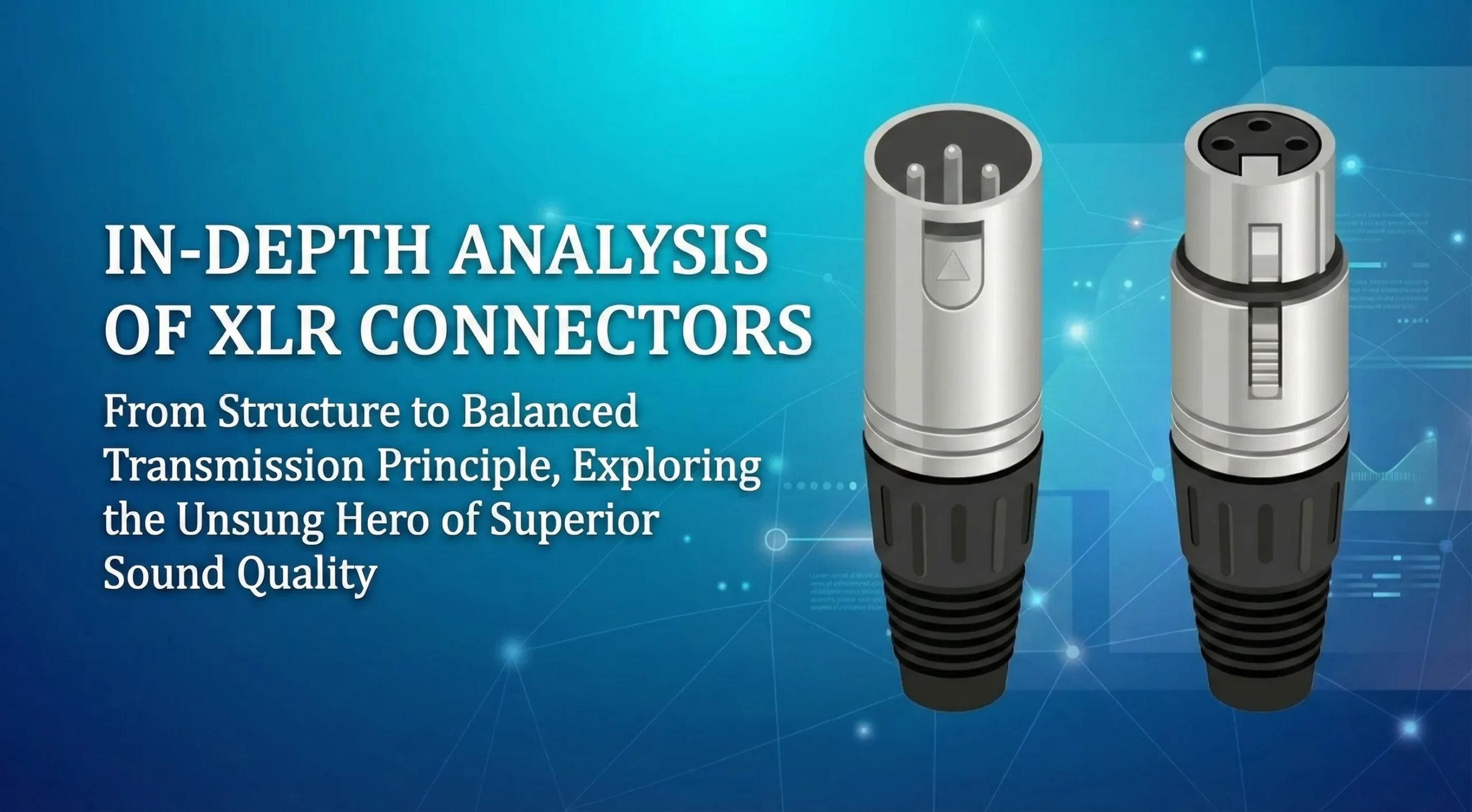
Audio connectors (commonly known as Phone Jacks) are defined by far more than their physical size. Behind each connector lies