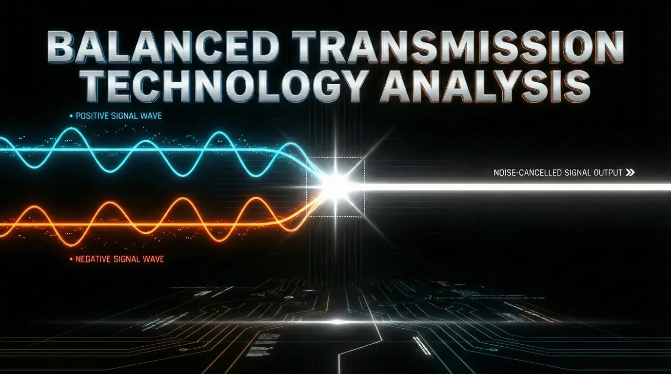
Balanced Transmission Technology Analysis
Unveiling the Core of Audio Transmission: Achieving High Noise Immunity with Balanced Systems In professional sound reinforcement, recording studios, and
Unveiling the Core of Audio Transmission: Achieving High Noise Immunity with Balanced Systems In professional sound reinforcement, recording studios, and
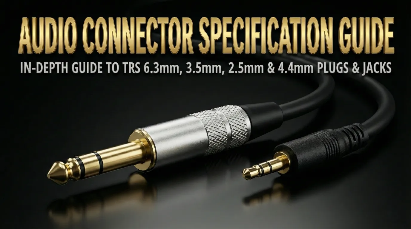
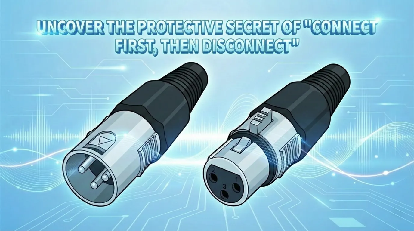
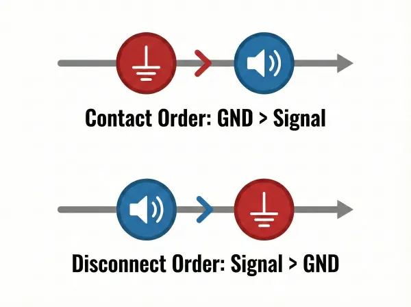
Audio connectors (commonly known as Phone Jacks) are defined by far more than their physical size. Behind each connector lies
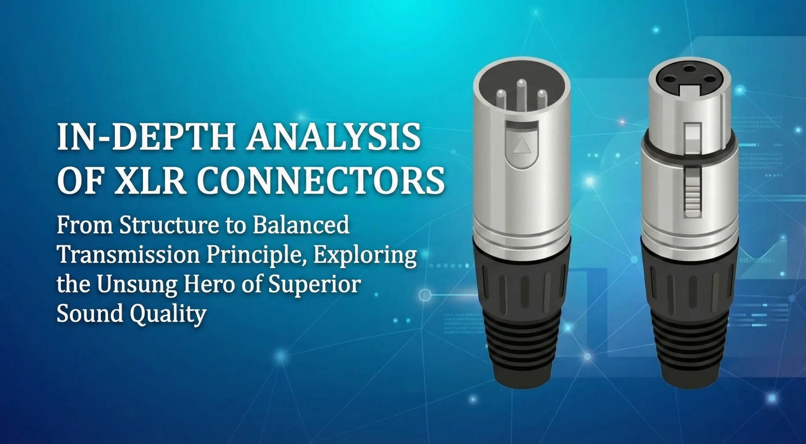
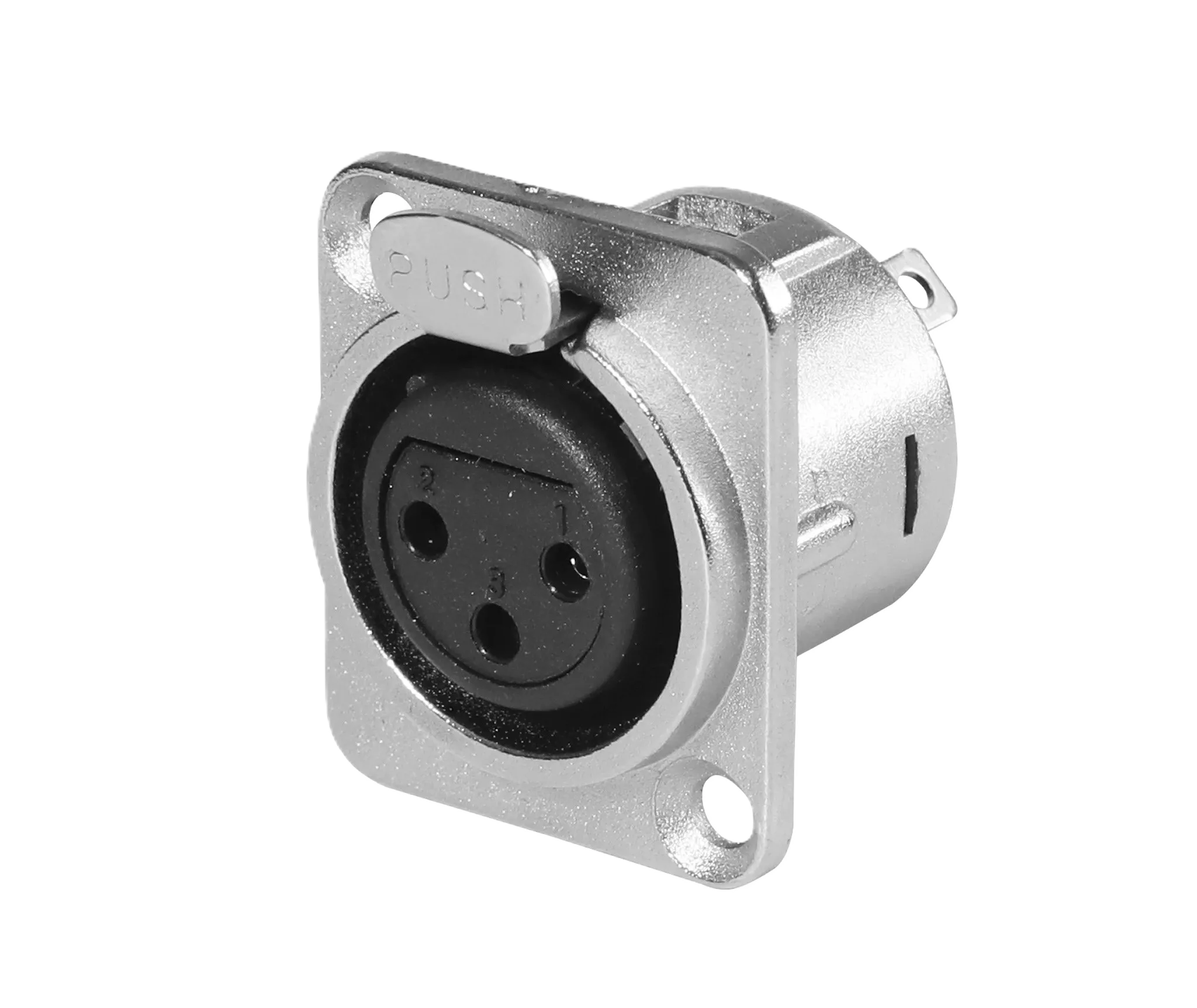
🌟Introduction: The Gold Standard of Professional Connectivity In professional audio, broadcast, and stage lighting systems, the XLR connector is far